


NOR Gate | A Tutorial with the Truth Table and Use Cases
A NOR Gate is a logic gate that has an output that is normally high (ON or 1), and goes low (OFF or 0) when ANY of its inputs are high.

The logic gate is the reverse, or complementary, form of the OR Gate. If you reversed the question from the example above, do you have anything in your hands? You’d get a yes response if they had something in their left, right, or both hands. That’s the OR Gate.
NOR gates are commonly used in digital circuits to perform arithmetic and data processing operations.
The NOR Gate (Not OR)
The gate is a combination of the following:
- OR Gate: Produces a high (ON or 1) output if ANY outputs are high
- and the NOT Gate: aka the inverter, produces an output opposite to its input.
Thus the name, Not OR (NOR).
*fyi, you’ll see the following terms are used interchangeably
1 | HIGH | ON
O | LOW | OFF
Here’s what it looks like when put in sequence.

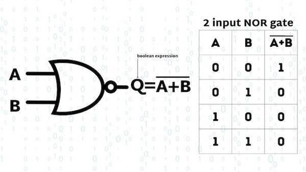
Boolean expression for a NOR Gate
The logic expression for a NOR gate represents Logical Multiplication performed on the complement of the inputs, which is denoted by a plus sign ( + ). The NOT function is represented with an overline ( ‾‾ ) , indicating logical negation. So, the Boolean expression for a NOR gate is A + B = Q. In simple terms, if both inputs A and B are false (NOT true), then the output Q is true.
A 2-input NOR Gate can be defined as:
“If both A and B are NOT true, then Q is true”
For quick reference, or when there are more inputs, that’s when you’ll want to check out the Truth Table.
Truth Table of the NOR Gate
The truth table of an NOR gate summarizes its behavior for all possible input combinations. Truth tables for NOR gates aren’t the most helpful, because any high input will produce a low output, but for clarity's sake, let's see what a NOR Gate Truth Table looks like.
2 input NOR Gate
As mentioned above, the 2 input NOR Gate is naturally in a HIGH state and will stay that way unless any of its inputs are HIGH.
3 input NOR Gate
And the same goes for the 3-input NOR Gate, any HIGH input will produce a LOW output. Otherwise, the output will be HIGH.

Basic Logic Gates Truth Table
For comparisons sake, here’s what a 2-input truth table looks like for the other basic logic gates.

Applications of the XOR Gate
NOR Gates are used mainly in electronic circuits that perform arithmetic operations and data checking such as Adders, Subtractors or Parity Checkers, etc.
Commonly available digital logic NOR gate IC’s include:
TTL Logic NOR Gates
- 74LS02
- 74LS27 Triple 3-Input
- 74LS260 Dual 4-Input
CMOS Logic NOR Gates
- CD4001 Quad 2-Input
- CD4025 Triple 3-Input
- CD4002 Dual 4-Input
And while we’re here, the pinout for the 74LS02 Quadruple 2-Input NOR Gate

Let’s take a look at the pinout for the CD4025 Triple 3-input NOR Gate

A few of the NOR Gate applications are:
- Combinational circuits such as multipliers
- Multiplexers
- Half and full adders
- Ripple-carry adders
Now that we know what they are used for, how does NOR compare with the other logic gates?
Comparing NOR with Other Logic Gates
As a quick overview, here are the main differences between NOR and the other basic logic gates, like AND, OR, and NOT Gates.
- AND Gate: Produces an HIGH output when all of its inputs are at logic level HIGH. In contrast, the NOR gate produces an HIGH output only when all of its inputs are LOW.
- OR Gate: Produces an HIGH output when at least one of its inputs is at logic level HIGH. On the other hand, the NOR gate produces aHIGH output only when all of its inputs are LOW. The NOR gate is the inversion (NOT) of the OR gate.
- NOT Gate: Also known as an inverter, a NOT Gate reverses the logic level. Input HIGH, output LOW. Input LOW, output HIGH. NOR is the combination of an OR gate followed by a NOT gate, producing the reverse of the OR gate's output.
- XOR Gate: Produces a HIGH output when the inputs are different and LOW when they are the same. The NOR gate, on the other hand, produces a HIGH output only when all of its inputs are LOW.
- NAND Gate: Produces a HIGH output unless all of its inputs are HIGH. In comparison, the NOR gate produces a HIGH output only when all of its inputs are LOW. The NOR gate is the inversion of the NAND gate.
- XNOR Gate (Exclusive-NOR gate): Produces a HIGH output when the inputs are the same and LOW when they are different. The NOR gate, however, produces a HIGH output only when all of its inputs are LOW. The NOR gate is not directly equivalent to the XNOR gate, though they are both naturally in a HIGH state.
The NOR Gate in Digital Logic | Final thoughts
Understanding the NOR gate is an important step in understanding how digital devices process information, and it provides a solid foundation for further study in electronics and computer science.
If you’re looking to continue your study, we wrote a bunch of other articles on the topic of Logic Gates. Dive in!